Step 1
Perform an actual machine diagnosis service support check.
Step 2Do you have a scan tool (KW communication)?
Step 3
1. Connect the scan tool.
2. Start the engine.3. Use the scan tool to check the “PCV F / B” display.
Step 4
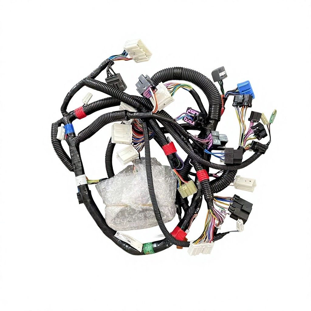
1. Use the breaker box or DMM to check whether the conditions below are present in the GND circuit between the ECM and boost temperature sensor. See the Breaker Box Inspection Procedure. Note:If there is no breaker box, see the Inspection procedures for sensors on actual machine.
• Short circuit with GND
• Disconnection
• High resistance
2. Repair or replace as necessary if a problem is detected.
Step 5
1. Use the breaker box or DMM to check whether the conditions below are present in the circuit between the PCV and ECM. See the Breaker Box Inspection Procedure.
Note:power supply circuit. If there is no breaker box, see the Inspection procedures for sensors on actual machine
• Short-circuit between terminals
• Short-circuit with power supply circuit or ignition power supply circuit.
2 Repair or replace as necessary if a problem is detected.
Step 6
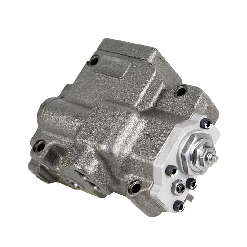
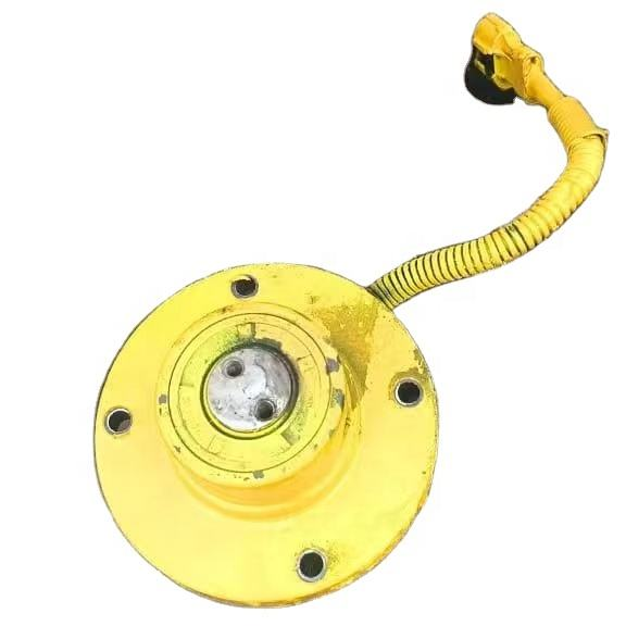
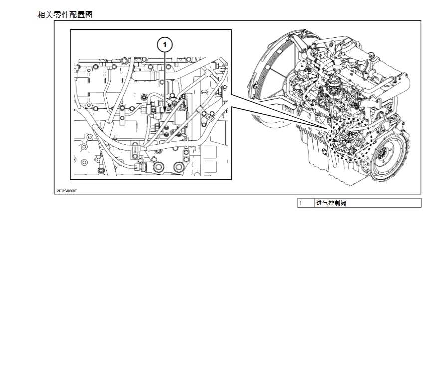
Inspect the PCV main unit.
1. Turn the key switch OFF .terminal.
2. Remove the harness from the PCV.
3. Measure the resistance at the PCV connector
Step 7
Replace the supply pump PCV. Note:work procedures. See the “Engine” section in The Service Manual for the
Step 8Recheck the diagnostic trouble code.
1. Connect all harnesses.
2. Delete the diagnostic trouble code. See the service support DIAG (trouble diagnosis) screen for information on deleting diagnostic trouble codes.
3. Turn the key switch “OFF” for at least 10 sec.
4. Start the engine and perform a test drive under the “Preconditions when diagnostic trouble code is set”.
5. Confirm the diagnostic trouble code.
Step 9
Is there an EMPS? No
Step 10
1 Check the ECM software version
2. Perform rewriting if updating the ECM software version is necessary.“How to Use EMPS”. For details on checking the ECM and the rewriting, see
Note: When ECM replacement or rewriting is performed, perform EGR learning.[EGR learning method]
1. Turn the key switch “ON”.
2. Turn the key switch “OFF”.
3. Wait about 10 sec.
Ste 11
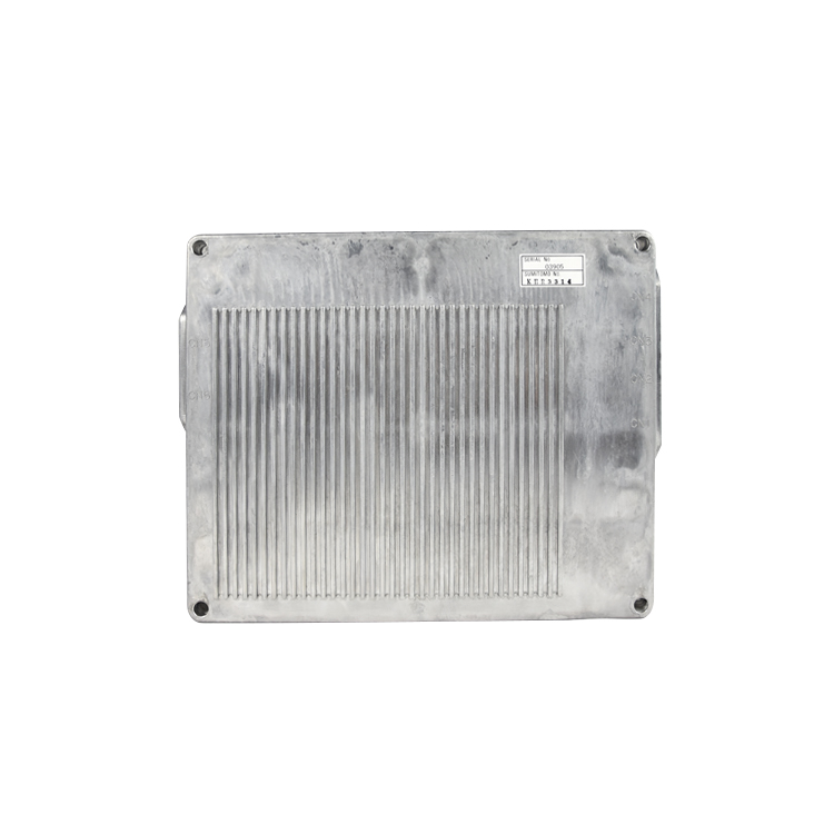
Replace the ECM.
Note: When ECM replacement or rewriting is performed, perform EGR learning. [EGR learning method]
1. Turn the key switch “ON”.2. Turn the key switch “OFF”.
3. Wait about 10 sec.
Step 121. Recheck the diagnostic trouble code.
2. Delete the diagnostic trouble code. See the service su ort DIAG (trouble diagnosis) screen for information on deleting diagnostic trouble codes,
3. Turn the key switch “OFF” for at least 10 sec.
4. Start the engine and perform a test drive under the “Preconditions when diagnostic trouble code is set”.
5. Confirm the diagnostic trouble code
Step 13
Check that no other diagnostic trouble code has been detected.
• Main relay power supply voltage is 16 V or higher.
• DTC: 0090, 0092, 1292 is not detected.
• 300 min or more, or actual rail pressure exceeds target rail pressure.
If an intermittent problem is suspected, the cause may be one of the following.
• Harness connector connection problem
• Harness routing problem
• Breakage in harness covering due to friction
• Wire disconnection within harness covering
In order to detect these causes, the following inspection is necessary.
• Harness connector and ECM connector connection problem
- Terminal has come out from connector
- Connection between non-matching terminals
- Damage to connector lock
- Terminal and wire connection problem
• Harness damage
- Inspect the external appearance to check for any harness damage.
- While moving the connector or harness related to a sensor, confirm the display of the related item in the scan tool data display. The display change shows the trouble location.
-