What's excavator hydraulic valve?
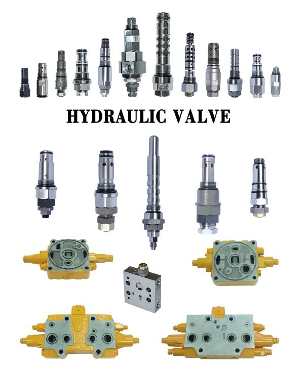
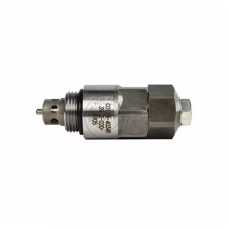
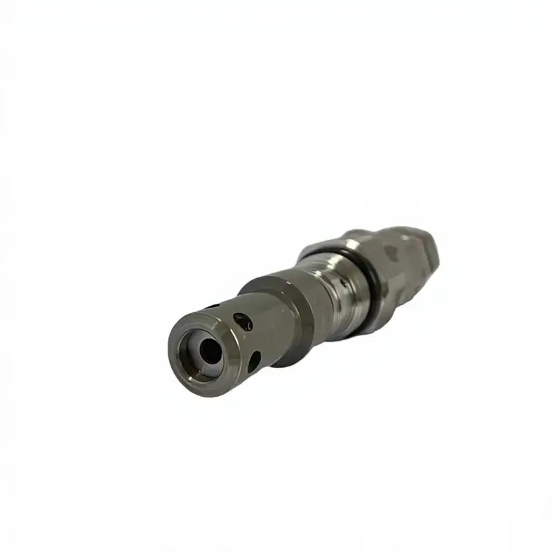
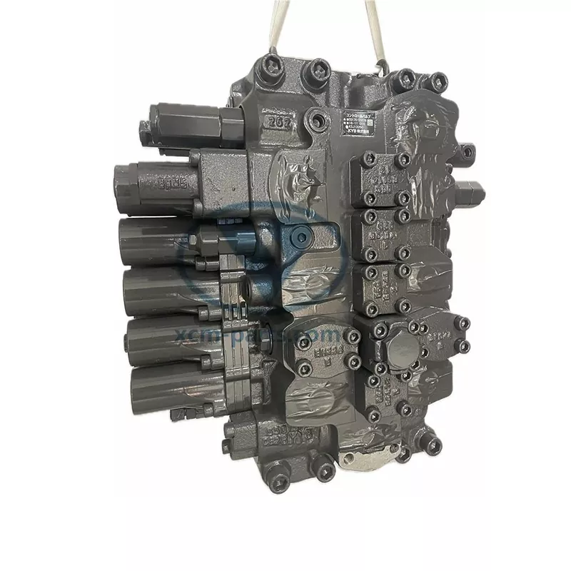
The hydraulic system of an excavator is typically powered by a main pump, which distributes pressurized fluid to various actuating components through an integrated multi-way valve block. Within this architecture, threaded cartridge valves serve as modular functional elements embedded in the valve body, undertaking essential roles such as pressure limitation, directional switching, flow regulation, and load holding. In the valve block of a medium-sized excavator, dozens of cartridge valves of diverse types are routinely integrated—including relief valves (pressure control valves), solenoid-operated directional valves, check valves, pilot-operated directional valves, and flow control valves—thereby enabling precise control over force, velocity, and operational safety across the entire system.
What's hydraulic valve functions?
Hydraulic valves constitute the core control elements of an excavator's hydraulic system, functioning analogously to the neural regulatory center of the human body. Their primary responsibility lies in precisely governing the direction, pressure, and flow rate of hydraulic oil. In excavator applications, hydraulic valves are predominantly deployed across three critical operational circuits:
-
Boom and arm control circuit: By modulating the extension and retraction of hydraulic cylinders, the valves enable precise actuation of the boom and dipper stick, facilitating fundamental tasks such as digging, loading, and lifting.
-
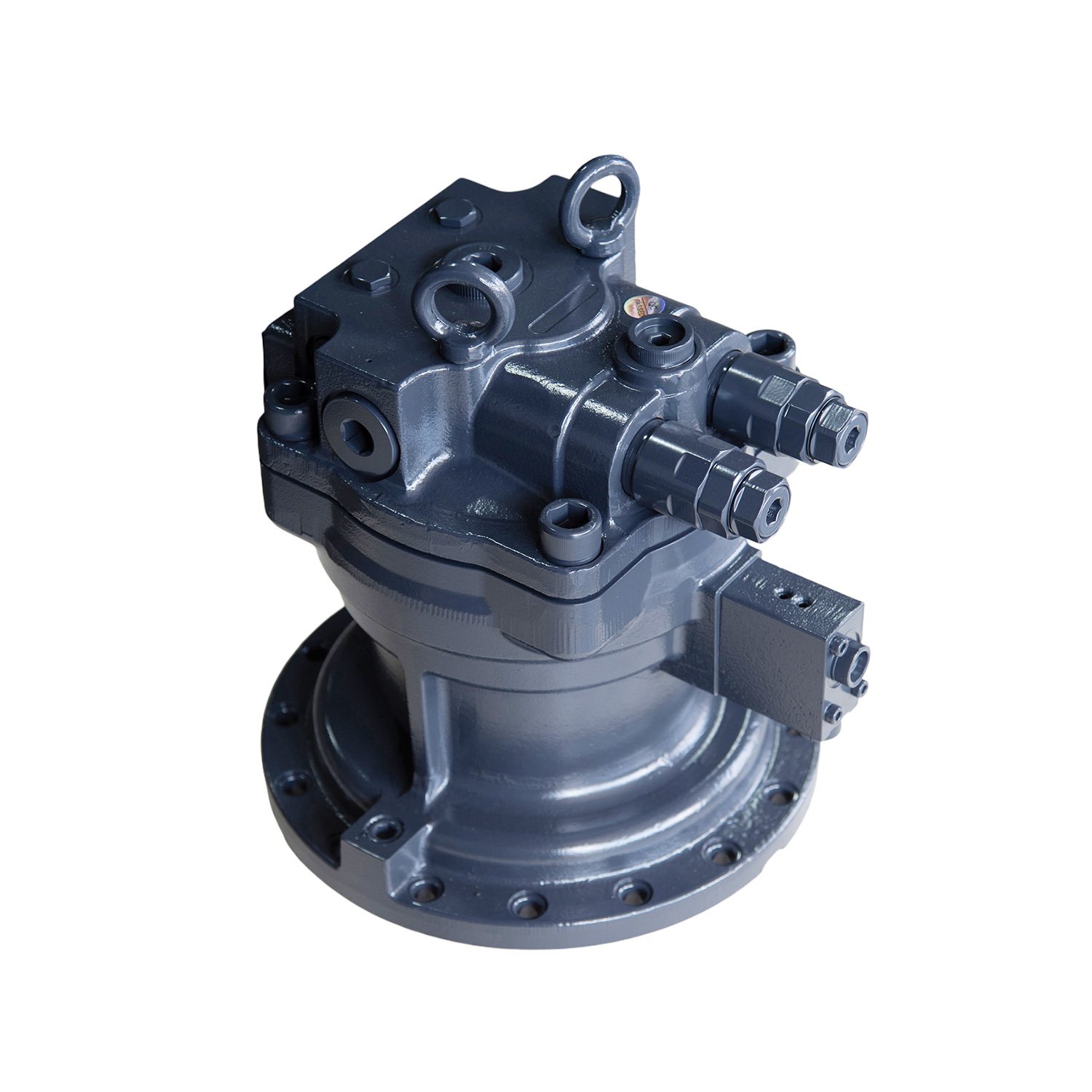
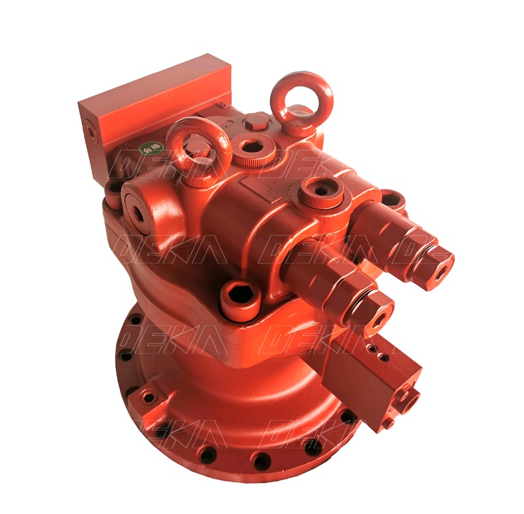
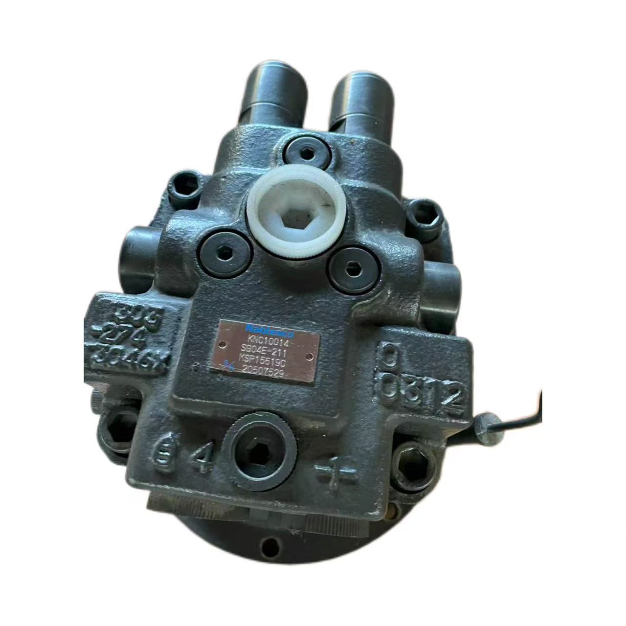
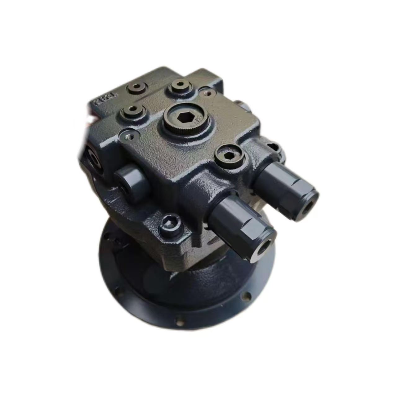
Slewing control circuit: The valves regulate the rotational direction and speed of the slew motor, thereby enabling precise 360° positioning and orientation adjustments of the upper structure relative to the undercarriage.
-
Traction drive circuit: Hydraulic valves distribute hydraulic power to the left and right track drives according to operational commands, thereby executing forward motion, reverse motion, and steering maneuvers.
How is hydraulic valve working?
During the operational cycle of an excavator, hydraulic valves respond to pilot control signals by adjusting spool displacement, thereby enabling precise modulation of actuator motion. Taking a standard digging operation as an example, the control process can be delineated into four sequential hydraulic phases:
-
Command Input Phase: Pilot control signals generated by the operator's handle are transmitted to the hydraulic valve, inducing axial displacement of the spool and opening the designated flow passages.
-
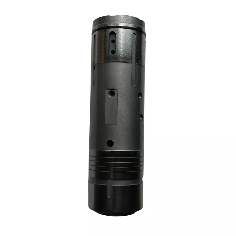
Actuation Phase: Pressurized fluid flows through the metering orifice of the spool into the cylinder working chamber, establishing a pressure differential that drives the piston rod to extend along a predetermined trajectory.
-
Regulation Phase: The spool undergoes fine positional corrections within its travel range, altering the orifice area to modulate flow gain, thereby achieving precise control over actuator velocity and output force.
-
Reset Phase: Upon completion of the stroke, the spool returns to its neutral position under pilot pressure differential or spring force, interrupting the pressure supply and allowing fluid from the cylinder chamber to drain back to the reservoir through the valve return passage, returning the system to a standby state.