During the initial visual inspection of the engine compartment interior and the frame structure for conducting diagnostic steps, a thorough visual inspection of the engine compartment interior and the frame structure should be carried out. Usually, problems can be solved without taking any other steps through a visual inspection. When conducting the visual inspection, follow the following instructions.
· Check all air hoses to ensure they have no punctures, cuts, or misaligned connections, and confirm the use of appropriate piping.
· Check the hidden and hard-to-see hoses covered by other component parts.
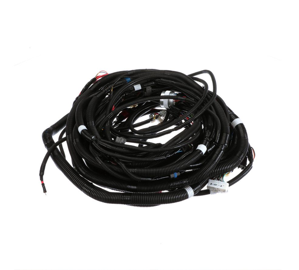
· Inspect all wiring harnesses within the engine compartment and frame structure to determine that the wiring connections are correct, without burned or worn areas, without fraying, without contact with sharp edges and high-temperature exhaust manifolds or pipes.
1. Confirm the maintenance status of the machine
Improper engine oil replacement or the use of engine oil with non-conforming viscosity may lead to blockages of the oil filter and fuel filter as well as sediment adhesion on the crankcase, which may result in main engine failures that remain undetected prior to the inspection via the main engine diagnostic system. Similarly, improper hydraulic oil replacement or the use of hydraulic oil with non-conforming viscosity may cause blockages of the suction filter or return oil filter, thus giving rise to corresponding failures. Main engine maintenance issues do not fall under the failure category (except for main engine failures). Nevertheless, as main engine diagnosis features higher accuracy, the main engine maintenance schedule shall be followed more stringently.
2. Non-original equipment manufacturer parts, commercially available components
All maintenance, assistance, diagnosis and adjustment operations are completed using original factory parts. Therefore, if a general commercially available sensor or switch is installed, it will cause diagnostic errors and display incorrect diagnostic trouble codes. If inappropriate commercially available electrical devices such as mobile phones, stereos or anti-theft devices are installed, they may emit EMI (Electromagnetic Interference) to the control system, which will generate erroneous sensor information and display diagnostic trouble codes. When conducting fault diagnosis, cut off the power supply of the commercially available components or disassemble them, then re-inspect the fault.
Important: If personnel without basic knowledge of the power transmission system perform the diagnostic steps, it may lead to incorrect diagnoses or damage to the components of the power transmission system, and they will not be able to conduct fault diagnosis related to the power transmission system. It is necessary to have a basic understanding of hand tools, such as diagnostic tools, in order to effectively use the service manual.
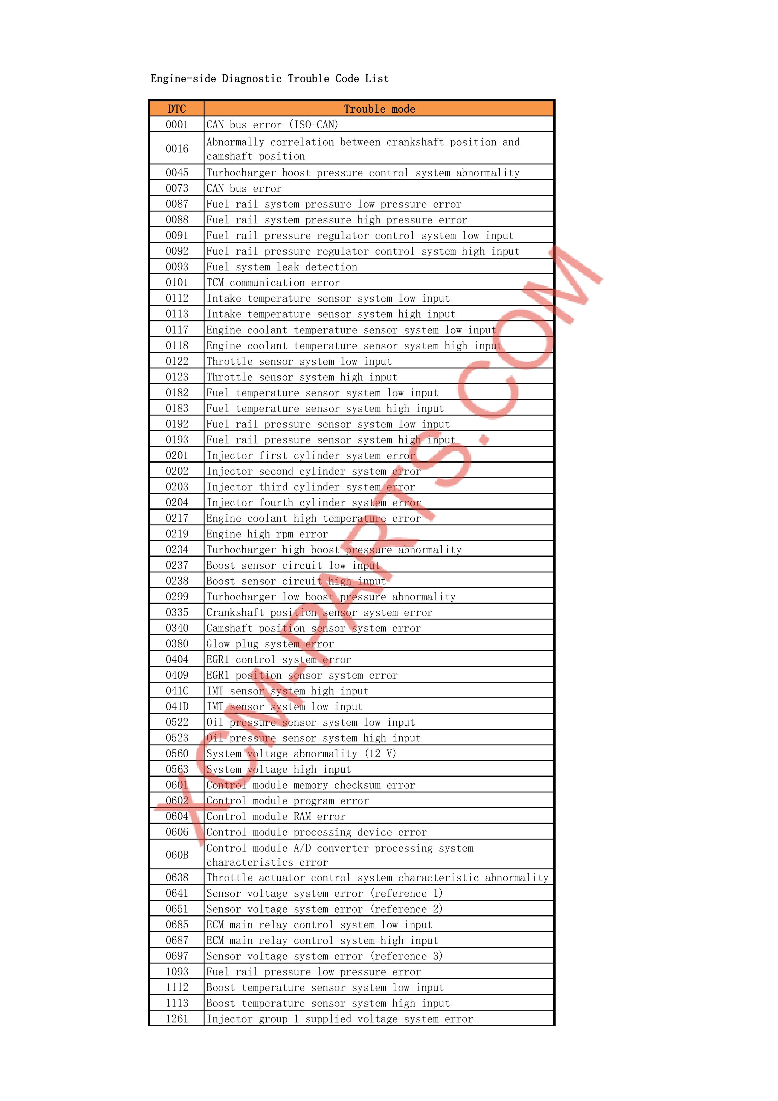
The machine diagnostic test is as follows regarding the types of fault diagnosis results.
1. The diagnostic fault codes that occurred due to previous faults under the following conditions are classified as "previous faults".
· The previous ignition cycle diagnostic test was completed.
· The machine passed the current ignition cycle diagnostic test.
· The identified faults during the diagnostic test are not currently present.
2. The diagnostic fault codes that occur under the current conditions are classified as "current faults".
· The previous ignition cycle diagnostic test was completed.
· The identified faults during the diagnostic test are currently present.
· A fault occurred during the current ignition cycle.
-